¶ NestStudio
NestStudio is a lightweight programming and collaborative control software designed for desktop CNC machines. With an integrated project-based workflow, intelligent toolpath algorithms, and a user-friendly interface, it delivers an efficient and smooth CNC experience for both beginners and professional users.
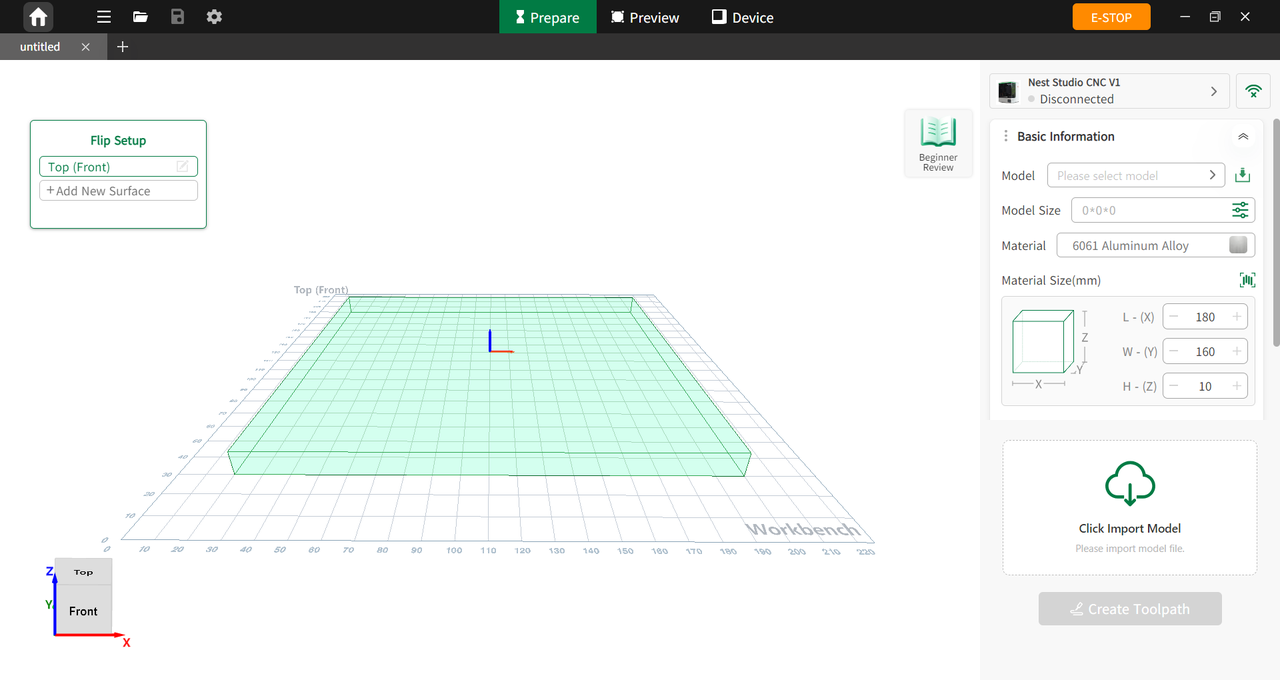
Figure 5-1 Overview
¶ System Requirements
| Item | Description |
|---|---|
| Operating System | Windows 10 64-bit or later Mac with Apple silicon Linux system with OpenGL 2.0 support |
| Processor | Intel i5 / AMD R5 or higher, with a clock speed greater than 2.4 GHz |
| Memory | 8 GB recommended |
| Storage Space | 8 GB or more available storage |
¶ Windows Download and Installation
¶ Windows Software Download
Scan the QR code below to download the Windows version of NestStudio.

¶ Windows Installation
-
Double-click the downloaded installer to begin installation.
-
When prompted with “Do you want to allow this app to make changes to your machine?”, select Allow and continue.
¶ macOS Download and Installation
¶ macOS Software Download
Scan the QR code below to download the macOS version of NestStudio.

¶ MacOS Installation
Drag the NestStudio application into the Applications folder to complete installation.
¶ machine Connection
¶ Wired Connection
Connect the computer to the machine using a compatible USB cable. View the IP address and pairing code on the machine touchscreen, then enter them in NestStudio.
¶ Wireless Connection
Connect the machine and the software to the same Wi-Fi network. View the IP address and pairing code on the machine touchscreen, then enter them in NestStudio.
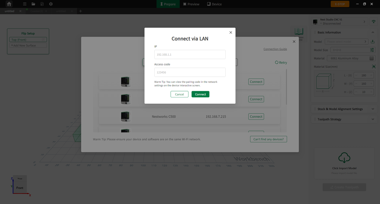
Figure 5-2 Wireless Connection
¶ Community Access
Users can visit www.worksbase.com to access the WorksBase official resource community and Online Academy for support. In the WorksBase, users can access a wide range of high-quality design resources and creative inspiration free of charge, and learn about machine operation, machining processes, and parameter settings to complete design and machining tasks more efficiently.
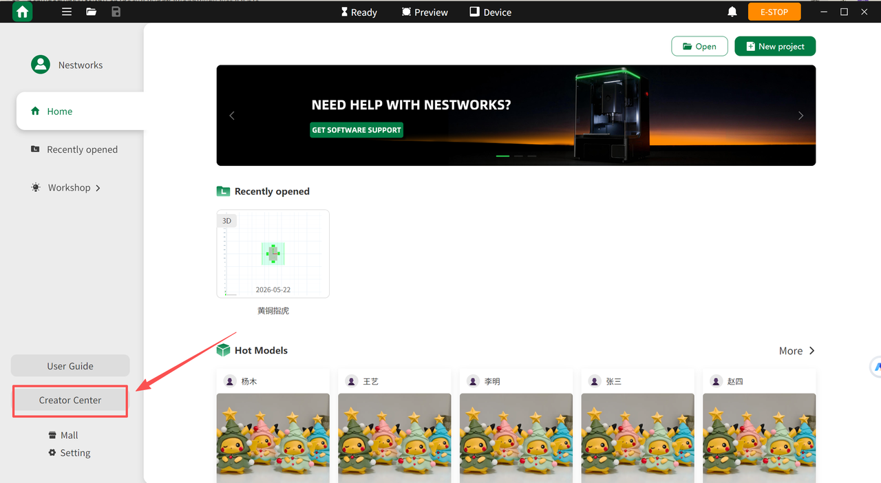
- Double-click the NestStudio to launch the software. If not installed, users can download it from the www.nestworks.ai .
- Click Creator Center on the left side to enter the WorksBase.
¶ Software Interface Overview
The main interface of NestStudio includes the main toolbar, menu bar, New Project and open entry , Recently opened and Workshop.
¶ Home
Account Login
Log into your NestStudio account to access points, wallet and earnings, and cloud storage.
Recent Projects
Quickly open projects that were recently edited or used.
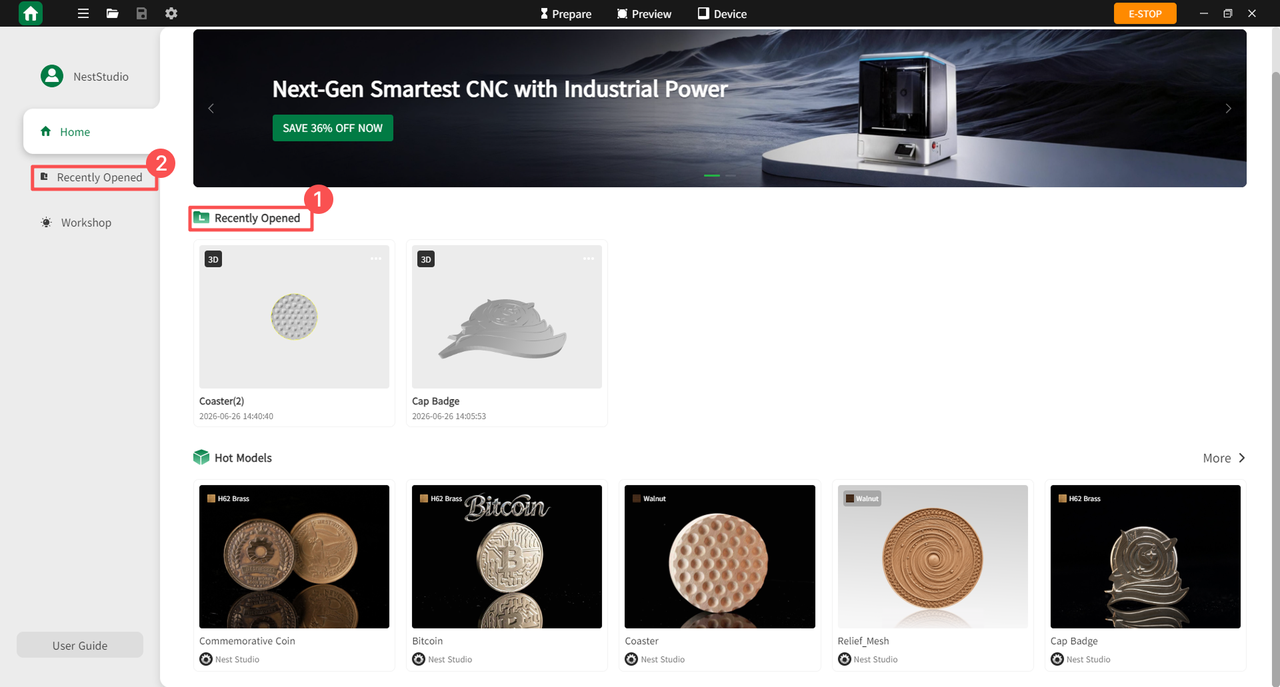
Figure 6-1 Recent Projects
Browse Hot Models
Browse hot models and click to open them directly.
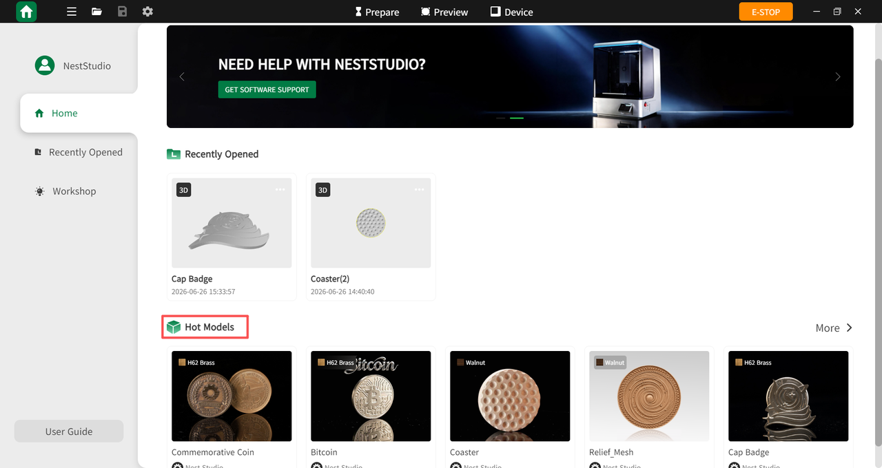
Figure 6-2 Browse Hot Models
Create New Project
Quickly create a new NestStudio project.
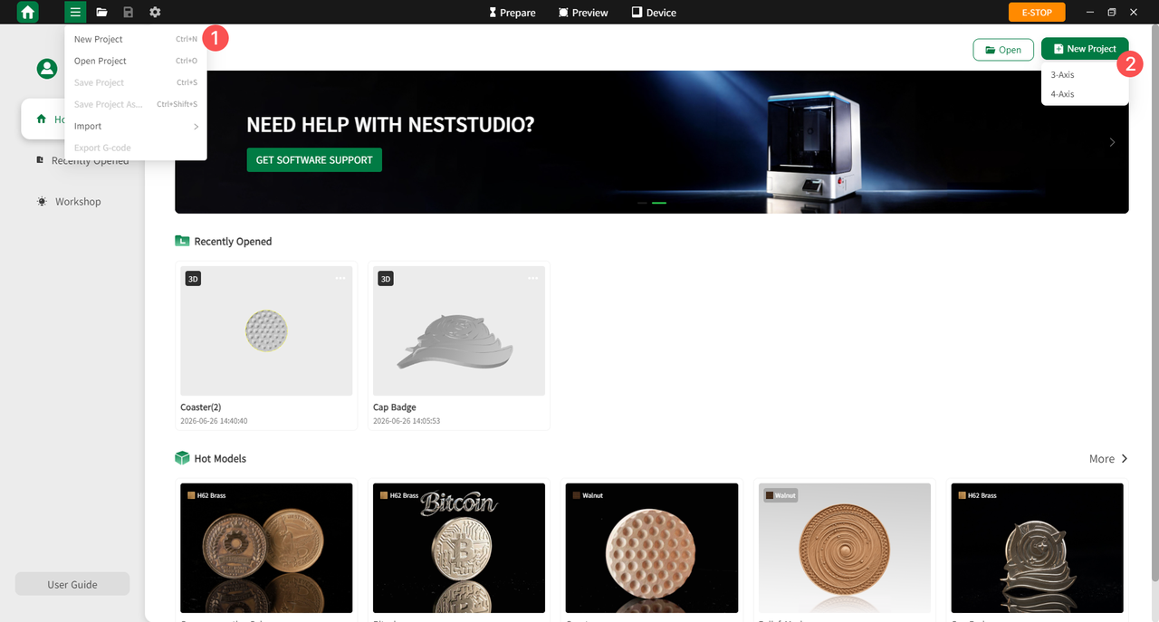
Figure 6-3 Create New Project
Open Local Project
Supports all NestStudio files, 3D files, and NestStudio project packages.
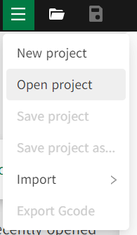
Figure 6-4 Home
Software Settings
Customize software preferences according to user requirements.
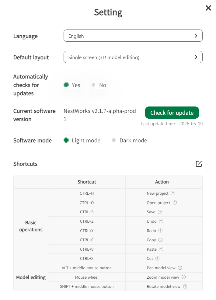
Figure 6-5 Software Settings
Window Controls
Minimize, maximize, or close the software window.
Cloud Storage Access
Click the user avatar to access cloud storage. You can manage the Drafts folder, view created directories, and synchronize the latest projects.
Home Page Layout
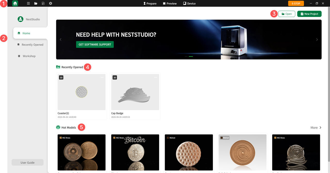
Figure 6-6 Home Page Layout
| No. | Feature | Description |
|---|---|---|
| 1 | Main Toolbar | Includes HOME, New Project, Import Drawing, Export Program, Save File, E-Stop, Account Settings, and Settings |
| 2 | Menu Bar | Includes Account Login, Home, Recent Files, Creative Workshop, User Guide, Creator Center and Marketplace |
| 3 | Open/New project | Open local files or create a new project |
| 4 | Recently opened | Quick access to recently saved files |
| 5 | Hot Models | Browse popular models and open files directly |
¶ Workshop
The Workshop provides a rich library of design assets, including artistic ornaments, bookmarks, coasters, keychains, reliefs, and trendy toys. Users can filter assets of interest and import them into projects for production.
Users can click the filter button on the right side of the page to quickly locate specific models, enabling efficient DIY creation.
¶ User Guide
Users can access the User Guide through the left menu bar on the Home page to master the core operations of NestStudio, obtain professional tool selection advice, and learn CNC machining knowledge to ensure the successful completion of the entire CNC process from design to finished product.
-
User Guide: Users can learn quick operation tutorials for NestStudio, including remote control and monitoring of equipment, selecting appropriate tools based on items, and correct material clamping methods.
-
Categorized Learning: Provides learning content for novice users or those wishing to understand CNC machining standard processes, including: how to align stock, how to align toolpaths, laser outlining operations, automatic centering methods for flat and curved stock, equipment calibration processes, and common troubleshooting such as device connection failure or file transmission failure.
¶ Prepare Page
Click Prepare to enter the ready interface, where users can precisely adjust parameters related to model size, material selection, and process settings.
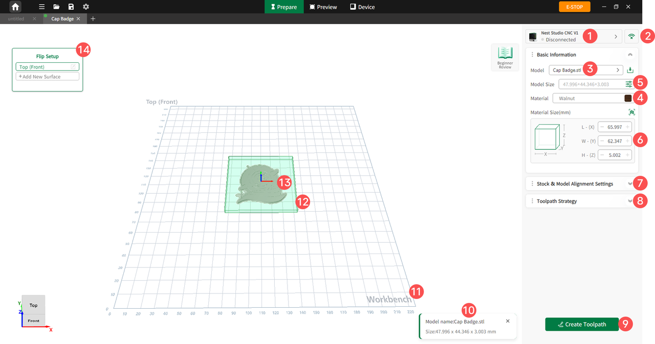
Figure 6-7 Ready Page
| No. | Feature | Description |
|---|---|---|
| 1 | Device Status | Displays the current connection status of the device. |
| 2 | Connect Device | If the device is not connected, users can click here to connect via wired or wireless methods. |
| 3 | Model | When multiple models are imported, users can select the desired model via the drop-down menu. |
| 4 | Material | Select machining materials and view CNC material instructions. When connected, scanning a material QR code automatically fills in material type and dimensions. |
| 5 | Model Size | Adjust the dimensions of the imported model. |
| 6 | Material Size | Manually configures the dimensions of the stock material. |
| 7 | Stock & Model Alignment Settings | Set the position and rotation angle of the model on the worktable. |
| 8 | Toolpath Strategy | Choose from One-Click Smart Milling, Custom Settings, or adjust advanced processing parameters. |
| 9 | Create Toolpath | Click to generate and preview the toolpaths for the model. |
| 10 | File Information | Displays information about the imported or opened file, including model name and size. |
| 11 | Workbench | Displays the visual representation of the machining worktable. |
| 12 | Stock View | Displays the visual representation of the raw material stock. |
| 13 | Model View | Displays the model view. A single model is shown in light green when no machining surface has been created. After a machining surface is created, the machining surface is highlighted in yellow. |
| 14 | Flip Setup | Sets the front face as the default machining plane, with the option for users to create a new machining plane. |
¶ Preview Page
Click Preview in the center of the top toolbar to enter the Preview interface. Users can review the generated toolpath effects, strategy parameters, and machining paths, and proceed directly to machining or export the G-code file.
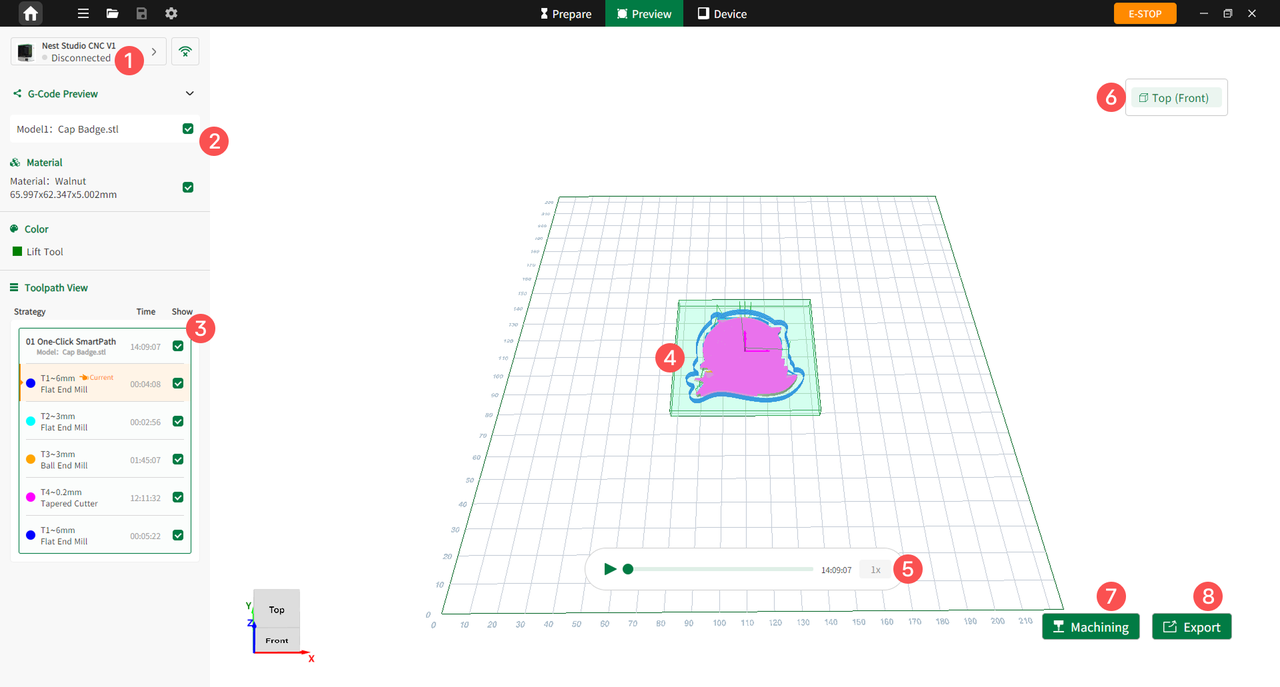
Figure 6-8 Preview Page
| No. | Feature | Description |
|---|---|---|
| 1 | Device Status | Displays the current connection status. If disconnected, users can click the icon on the right to connect via wired or wireless methods. |
| 2 | G-Code Preview | Allows users to show or hide the preview status of the model, material, and related display items. |
| 3 | Tool path View | Displays each machining step, including the strategy, estimated machining time, tool type, and tool visibility status. |
| 4 | Toolpath Preview | Displays the actual machining paths of the tool in the worktable view. |
| 5 | Playback Control | Controls the toolpath simulation playback, including play, pause, progress adjustment, and playback speed. |
| 6 | Top (Front) | Displays the current machining face. Users can switch to the specific face to be machined. |
| 7 | Machining | Starts machining when the device is connected. |
| 8 | Export | Exports the G-code file. |
¶ Device Page
Click Device to enter the Device interface. Users can monitor the machining video in real time, view processing step guides and progress, and perform quick equipment debugging and parameter intervention.
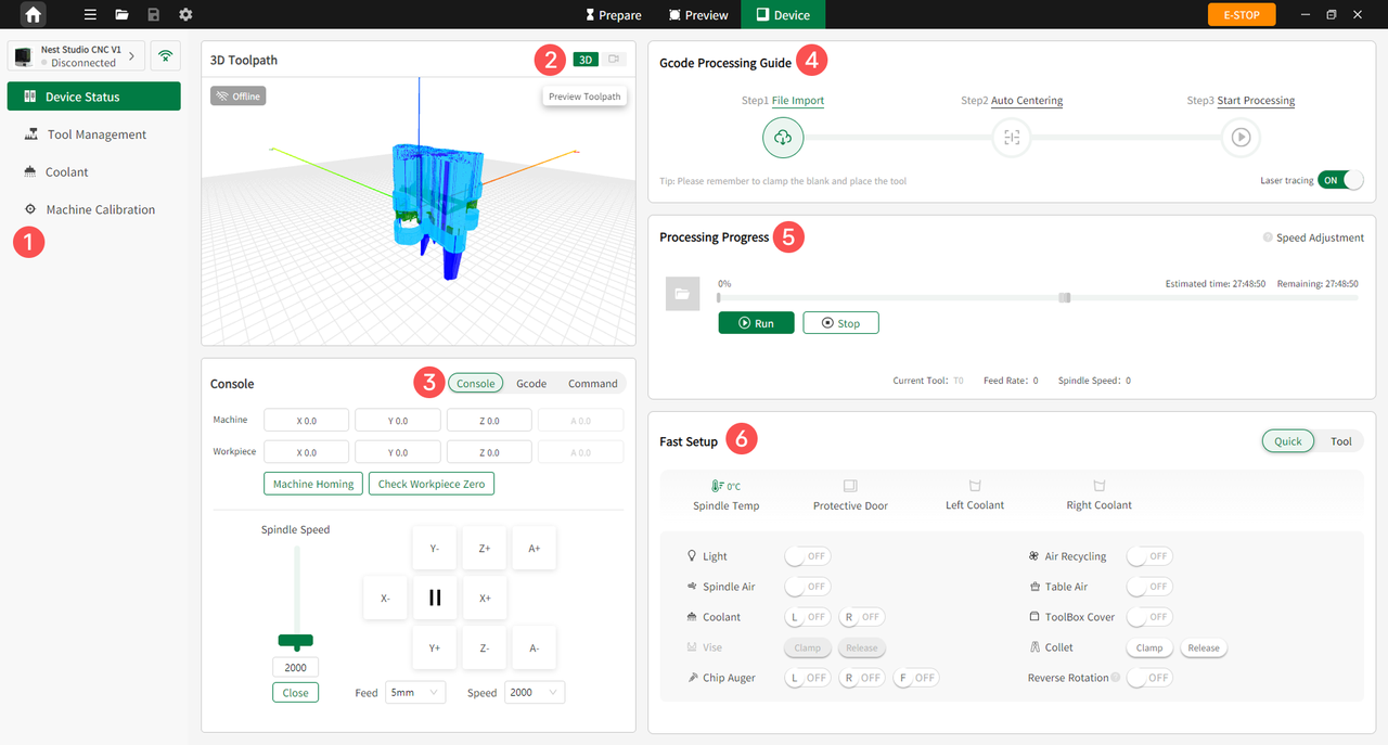
Figure 6-9 Device Page
| No. | Feature | Description |
|---|---|---|
| 1 | Left Menu Bar | Access features such as Device Status, Tool Management, Coolant Management, and Machine Calibration. |
| 2 | Machining Video Monitoring | Monitors the machining video in real time and previews the toolpath. |
| 3 | Console | Debug machine or workpiece coordinates, set machine home, check workpiece zero, and adjust spindle speed and feed rate. |
| 4 | G-code Guide | Guides users through the machining process: Import File > Workpiece Centering > Start Machining. |
| 5 | Machining Progress | Displays progress, including estimated and remaining time, as well as the current tool number, feed rate, and spindle speed. |
| 6 | Quick Debugging | Quickly control the machine, including turning the work light, air purification, spindle cleaning, worktable cleaning, spray cooling, tool magazine door, vise, collet, and chip auger on or off. It also supports tool setting, tool return, and zero position reset operations. |
¶ Tool Management
Click Tool Management to enter the Tool Management page. Users can read tool information, configure tool parameters, and manage tool life.
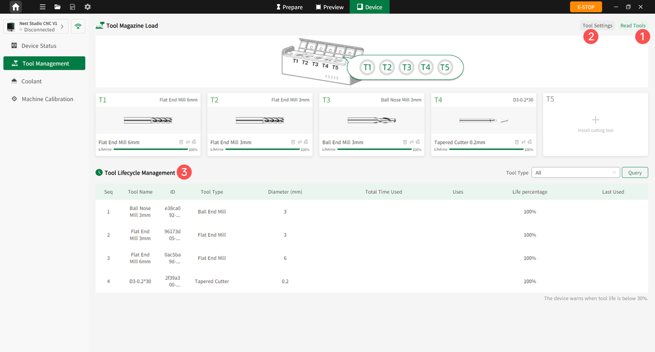
Figure 6-10 Tool Management
| No. | Feature | Description |
|---|---|---|
| 1 | Read Tools | After connecting the device, quickly read RFID information for the 5 tools in the tool magazine and display it on the interface. |
| 2 | Tool Settings | Customize tool parameters. |
| 3 | Tool Lifecycle Management | Displays the remaining tool life percentage. A warning is triggered when below 30%, allowing timely tool replacement. |
¶ Coolant Management
Click Coolant Management to view the remaining coolant levels in the left and right tanks. Users can also add or configure coolant settings.
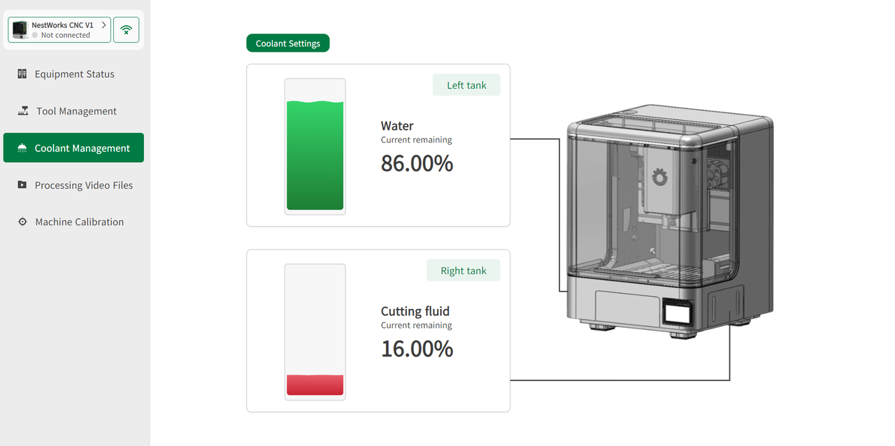
Figure 6-11 Coolant Management
¶ Machine Calibration
Click Machine Calibration in the left menu of the Device interface to access the Machine Calibration page. This interface is divided into two subpages: Device Information and Device Calibration, for viewing device status, parameters, and performing calibration operations.
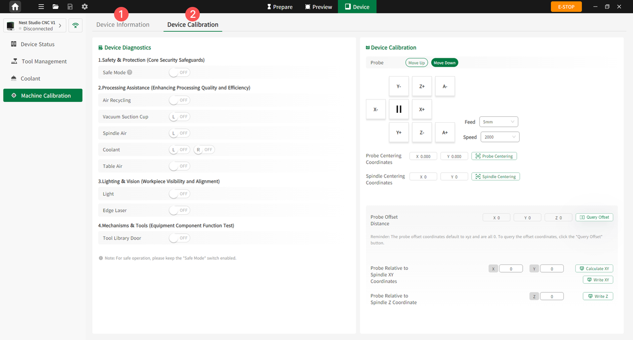
Figure 6-12 Machine Calibration
| No. | Subpage | Modules & Description |
|---|---|---|
| 1 | Device Information | Device Info: View device model, connection type, total operating hours, and firmware version; configure startup homing. Status Parameters: Monitor spindle core status, actual feed and spindle speed, machine coordinates and workpiece coordinates, machine status, current tool number, and G-code execution. Machine Parameters: View machine parameters, including maximum spindle speed and machine structure. |
| 2 | Device Calibration | Device Diagnostics: Check device status and component functions. Device Calibration: Adjust device precision and related parameters, such as probe centering coordinates and spindle centering coordinates. |
¶ Interface Functions
The NestStudio software primarily consists of four functional modules: Home, Prepare, Preview, and Device. Within the Prepare module, two modes are available: 3D, and 4-Axis. The software defaults to the 3D layout interface upon startup.
- 3D Mode: Used for conventional machining of three-dimensional models.
- 4-Axis Mode: Used for 4-axis simultaneous or fixed-axis (indexed) machining.
¶ Top Toolbar
- New Project
Click File > New Project, or click the Create New Project in the upper-right corner of the Home page to create a new project.
- Open Project
Click File > Open Project to select the file, or click the Open button in the upper-right corner of the Home page to browse for files.
- Save Project
Click Save Project to open a pop-up window. Users can choose to save the project file to either local computer or cloud storage.
- Save Project As
Click Save Project As to save the current project as a separate file with a new name or file path.
¶ Common Shortcut Functions
Import
Click Import to select the type of file to be imported:
- Import 3D Model: The user can choose to enter either the 3-Axis or 4-Axis layout interface based on machining requirements.
- Import Program: The system automatically redirects to the Device Status page.
Export Program
Click Export Program to export the finalized data into a G-code machining file.
Messages
Browse various system notifications here, including official announcements, interactive updates, and competition news.
¶ Model Import
¶ Import Methods
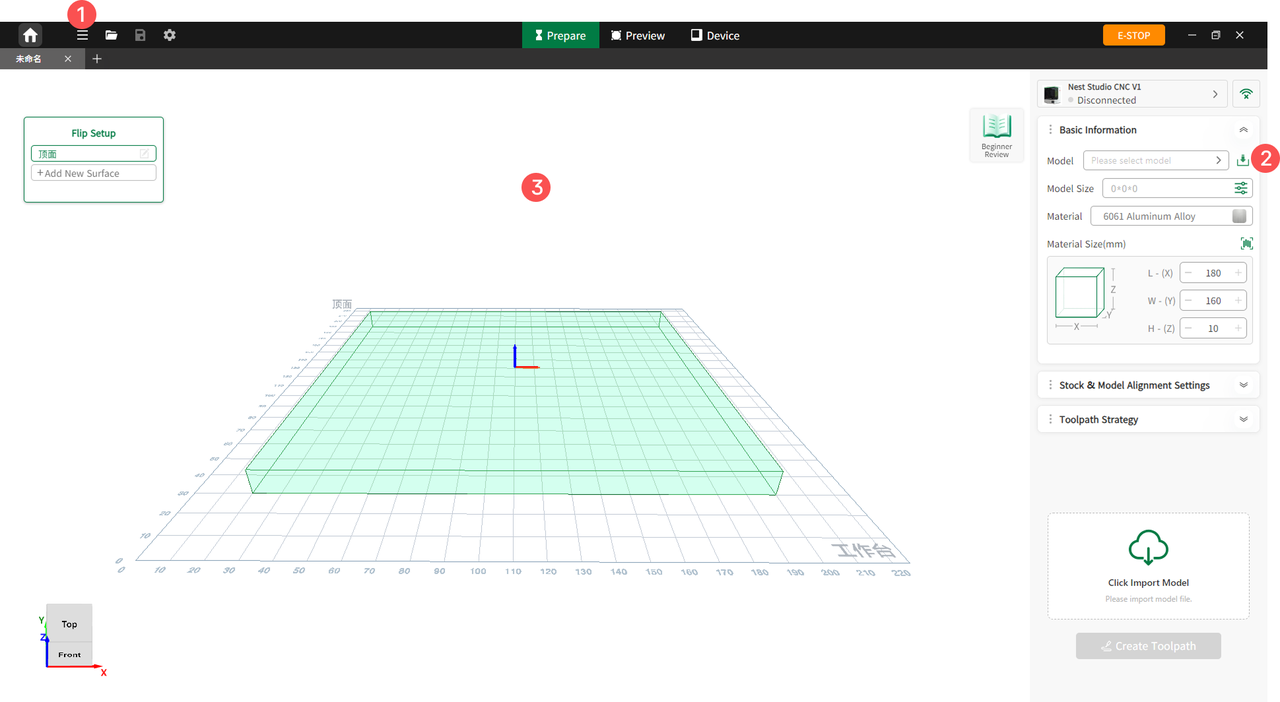
The software offers three methods to import models:
-
Toolbar Import: Click File (the second icon in the top toolbar), select Import, and choose based on the file type:
- Import 3D Model: Opens a pop-up window for the user to select either a 3-Axis or 4-Axis layout interface.
- Import Program: Automatically redirects to the Device Status page.
-
Parameter Panel Import: Click the Import icon in the right parameter panel to import a model.
-
Drag and Drop: Drag the target file directly from the computer desktop into the software workspace to complete the import.
¶ Supported File Formats
The software supports 3D files(.stl, .step, .stp) and NestStudio project packages (ZIP).
¶ Import Detection
Once a model is imported, the software automatically checks its format, size, and integrity, and displays the import results on screen:
- Import Successful: Displays the model name, dimensions, and other detailed parameters.
- Import Failed: Displays the specific error reason that caused the import to fail.
¶ Machining Parameter Settings
¶ Basic Information
Material Settings
Click Material to open the selection window and choose your target material. Additionally, when the machine is connected, users can scan the QR code on the material to automatically populate the material type and dimensions.
Alignment Settings
Users can adjust the relative position of the model within the stock using vertical and horizontal alignments:
-
Vertical Alignment: Adjusts the vertical positioning to the top face, center layer, or bottom face.
-
Horizontal Alignment: Adjusts the horizontal positioning to the left, center, or right.
Model Sizing
Click the dimension input box to open the model size settings panel. Users can modify the scale of the model by entering or adjusting the length (X), width (Y), and height (Z) values.
¶ Parameter Overview
The parameter settings panel consists of three core sections: Stock, Model, and Process.
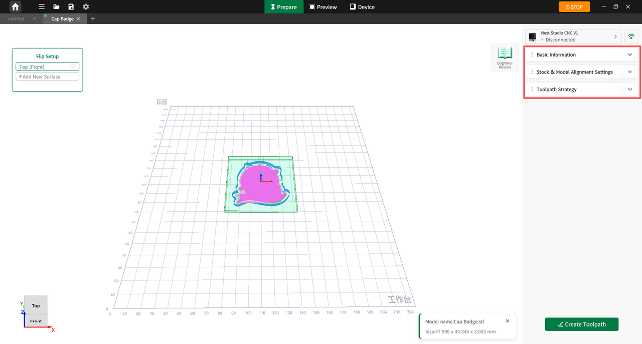
Figure 6-13 Parameter Overview
Stock
In the Stock tab, users can manually enter the length (X), width (Y), and height (Z) values of the raw stock, or use the Smart Material Detection feature to scan the material QR code for automatic input.
-
Stock Visibility Toggle: Allows users to visually check the relative position between the model and the stock, assisting in better machining judgments.
-
Stock Masking: When enabled, the stock acts as a boundary mask. It isolates the view to display only the toolpaths and model geometry within the stock boundaries while hiding anything outside, making it easier to troubleshoot overtravel or insufficient stock allowance.
Model
In the Model tab, users can adjust the model's position (X/Y/Z axes) and rotational orientation to ensure precise machining and maximize material utilization:
-
Position Fine-Tuning: Users can precisely adjust the front/back, left/right, and up/down position of the model relative to the stock using the +/- buttons or by typing values directly into the input boxes.
-
Rotation Settings: Users can manually input a specific rotation angle or click preset fixed values to orient the model around the X-axis, Y-axis, or Z-axis.
Process
After importing a model, the software automatically analyzes its geometry features and generates a default process strategy. The Process tab consists of two primary sections, Smart Milling and Advanced, which allow users to configure tools, supports, and coolant settings for individual models.
¶ Custom Settings
Smart Milling
Enter the Smart Milling interface to adjust core machining parameters based on production requirements, such as tool parameters (plunge angle, spindle speed, feed rate, stepover, etc.) and coolant status.
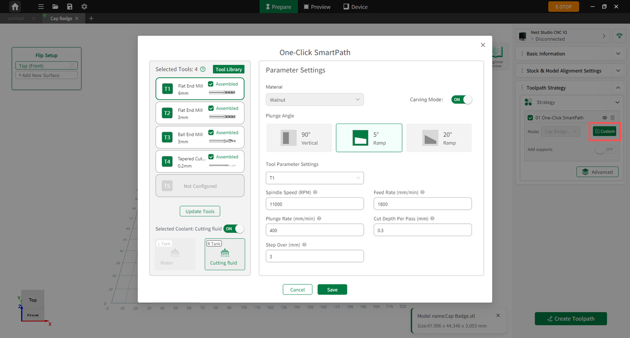
Figure 6-14 Custom Settings
Support Settings
Users can enable or disable tabs or supports here, as well as customize their height, length, and placement:
-
Smart Generation: Upon model import, the software automatically detects overhangs and structural proportions to place supports. If disabled, no supports will be generated.
-
Support Clearance: Users can define the specific offset gap distance between the support structure and the model body.
Advanced Settings
The Advanced module provides granular control over toolpath strategies, covering specialized machining methods such as tapping, chamfering, engraving, profiling, and pocketing:
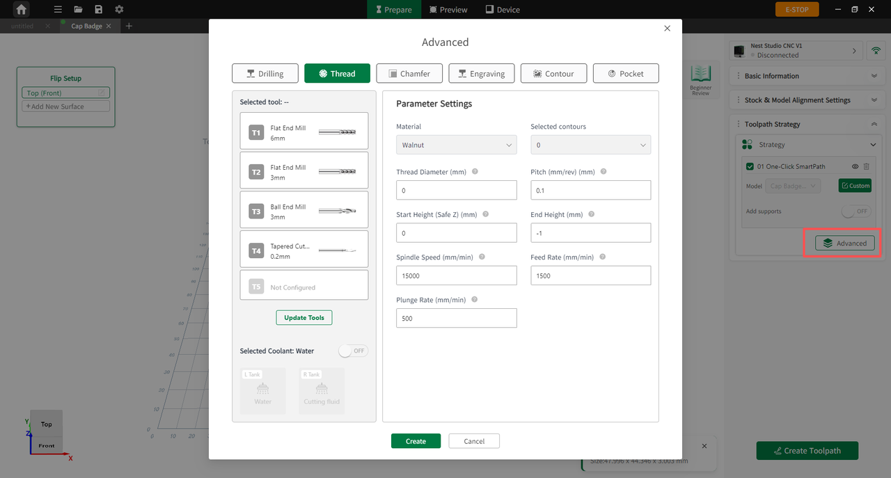
Figure 6-15 Custom Settings
-
Multi-Operation Machining: Advanced settings allow users to add specific machining operations (such as drilling) on top of the Instant Mill configurations, accommodating complex multi-tasking workpieces.
-
Smart Parameter Recommendation: In the Advanced mode, the software intelligently recommends optimal parameters for each specific operation type, removing the need for manual setup.
¶ 3D Toolpath Preview
In the Preview interface, users can review the dynamic toolpath trajectories, estimated machining time, and toolpath distribution. Click Export to export the G-code file.
The Preview interface consists of two main sections: G-code Preview on the left and the 3D Toolpath Simulation Viewport on the right. By default, the interface displays the simulation effects of all toolpaths combined; to inspect an individual toolpath, check only the target object.
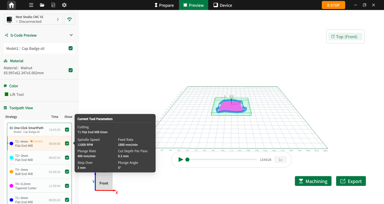
Figure 6-16 3D Toolpath Preview
¶ G-code Preview
Device Selection and Connection
The upper-left corner displays the currently connected device model and connection status. If the device is not connected, the interface displays a disconnected status.
Project Information
Displays the model name and current machining material information, including material type and dimensions.
Toolpath View
Consists of the operation strategy list and color legends:
-
Tool Information: Displays all toolpath operations, including the Smart Milling process and individual tool operations, with machining time for each operation.
-
Color Legend:
- Dark green: Retract path
- Light green: Reserved support
- Red: Support to be removed
¶ 3D Toolpath Simulation Viewport
Basic View
Users can rotate the model using mouse drag and zoom with the scroll wheel for multi-angle preview, allowing early detection of overcut or tool collision risks.
Toolpath Trajectory
Different colors are used to identify machining paths, allowing users to verify machining results in advance and reduce the risk of workpiece deformation.
Bottom Control
Click the play to view the machining simulation animation in real time.
¶ 4-Axis Toolpath Preview
In 4-axis mode, users can complete model import, machining parameter configuration, and toolpath generation in the Ready page.
After toolpath generation is completed, the system automatically switches to the Preview page. Users can inspect toolpath trajectories, tool parameters, and machining paths to verify the machining plan before processing.
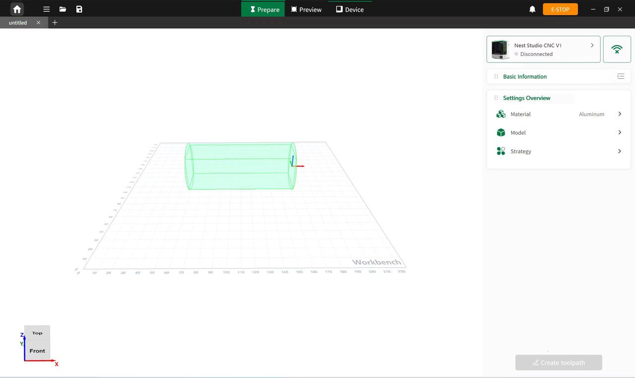
Figure 6-17 4-Axis Toolpath Preview
¶ Automatic Centering
Click Machining to open the automatic centering window. Users can follow the on-screen instructions to complete workpiece origin setup, without manual configuration.
Users may also switch to manual centering mode for workpiece origin setup.
¶ Laser Framing
Laser framing is used to check for processing offset errors in advance, preventing machining failures caused by stock clamping misalignments, and assisting in precise pre-machining positioning calibration.
¶ G-code Import
Users can import G-code files via the Import function in the second icon of the top toolbar or through the Device Program page.
After import is completed, detailed G-code information can be viewed on the Device Status page.
¶ Tool Management
The Tool Management page allows users to load tools, configure tool settings, and view tool life in real time.
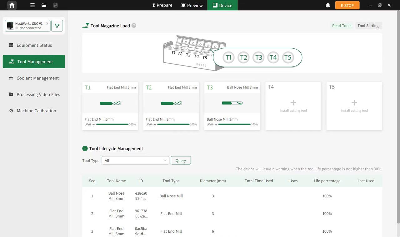
Figure 6-18 Tool Management
¶ Tool Loading
-
Click Read Tool to automatically read and register tool information when the device is connected.
-
Click Tool Settings to open the settings window for adding tools, editing tools, and resetting the tool magazine zero position.
-
The tool card area displays tool type, diameter, and life information. New tool parameters can also be added in empty card slots.
¶ Tool Life Management
The tool life list displays tool life percentage and recent usage time.
When the life of a tool drops below 30%, the software automatically triggers a warning to assist with tool life management.
¶ Coolant Management
In the Coolant Management page, users can monitor the coolant level of the left and right tanks in real time, and configure coolant parameters.

Figure 6-19 Coolant Management
When coolant level is sufficient, the level indicator appears green. When coolant level is low, the indicator appears red and enters warning status. Refill coolant promptly when necessary.
¶ Machine Calibration
The Machine Calibration page includes the Device Information and Device Calibration modules. The Device Information page displays device status and operating information, while the Device Calibration page allows hardware diagnostics and parameter adjustment to improve machining accuracy and stability.
Figure 6-20 Machine Calibration
¶ Device Information
Basic Device Information
Displays device model, connection method, total operating time, and firmware version.
Users can also configure automatic homing and check firmware versions.
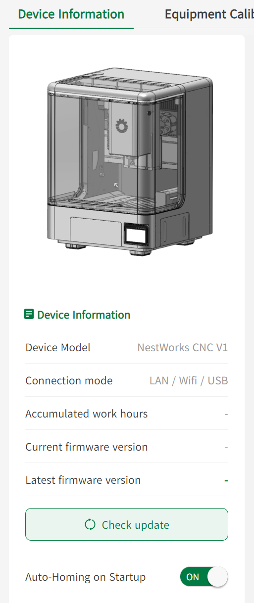
Figure 6-21 Device Information
Status Parameters
Displays real-time device status parameters, motion parameters, and machine parameters.
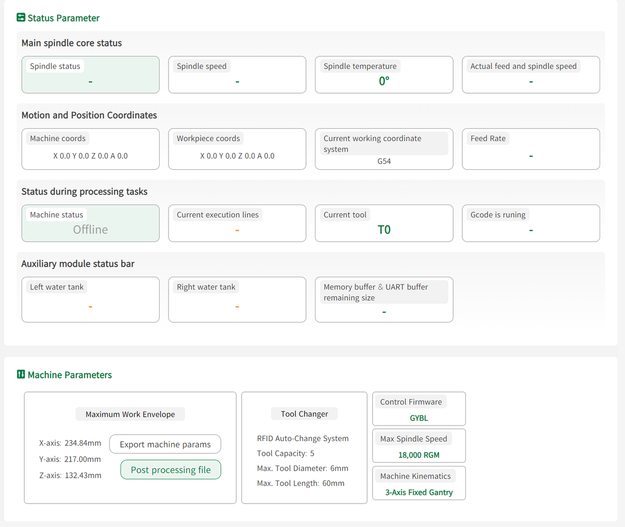
Figure 6-22 Device Information
¶ Device Calibration
Allows precision calibration and parameter adjustment to correct positioning deviations and improve machining safety and accuracy.
Device Diagnostics
-
Safety Mode
Enables device safety protection. Keeping this function enabled during machining is recommended. -
Machining Assistance
Controls functions such as air purification, vacuum suction, spindle cleaning, coolant, and worktable cleaning.When enabled, it helps improve chip removal and cooling performance.
-
Lighting and Vision
Controls lighting and framing laser functions for workpiece inspection and positioning verification.
-
Mechanism and Tools
Controls tool magazine opening and closing for tool replacement and maintenance.
Device Calibration
Users can manually adjust the upward and downward positions of the touch probe and correct probe positioning errors to improve centering accuracy.
¶ Task Machining
After G-code import is completed, the system automatically switches to the Device page. Users can preview 3D toolpaths, debug tools, and monitor machining progress online.

Figure 6-23 Task Machining
¶ 3D Toolpath
Displays the 3D model and toolpath trajectory in real time for overcut inspection and collision prevention. Users can switch to camera mode for live machining monitoring.
Figure 6-24 3D Toolpath
¶ Console
Provides coordinate display, manual axis movement, spindle control, and zero reset functions for manual workpiece alignment and device debugging.
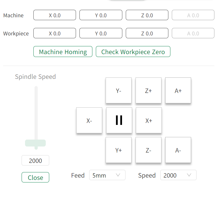
Figure 6-25 Console
¶ G-code Machining Guide
Users can complete the machining workflow with one click according to the machining instructions displayed on the page.
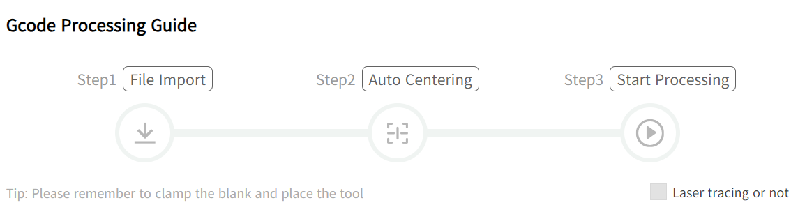
Figure 6-26 G-code Machining Guide
¶ Quick Device Adjustment
Allows quick control of auxiliary device components and inspection of core operating status for pre-machining debugging and safety checks.
¶ User Account
Click the [Icon] to log into an account, unlocking features related to points, wallet, earnings, and cloud storage.
¶ Login
Registered users can click Login and sign in using email and password.
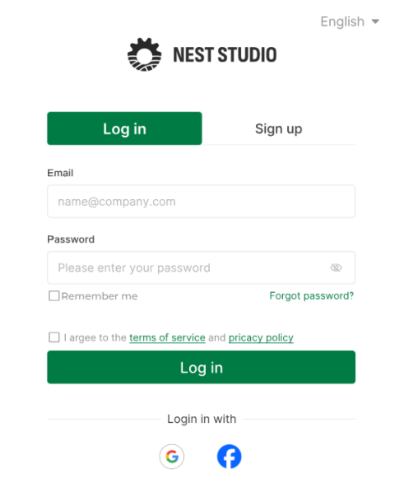
Figure 6-27 Login
¶ Register
When using the software for the first time, click Register to create an account. Enter an email address and complete registration using the verification code received via email.
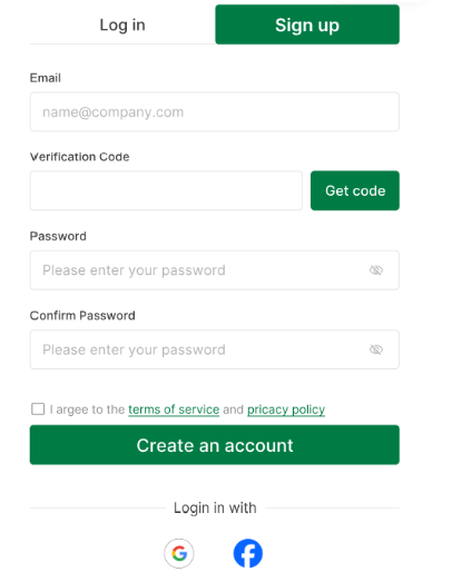
Figure 6-28 Register
¶ Password Recovery
If the password is forgotten, users can recover or reset the password through email verification.
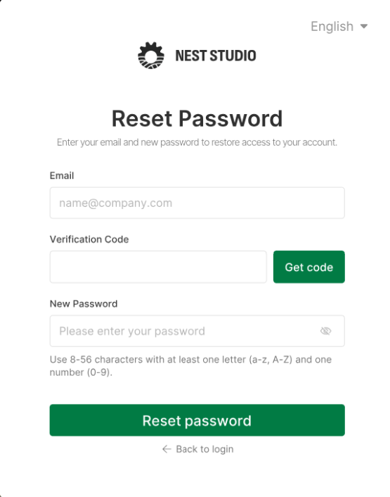
Figure 6-29 Password Recovery
¶ Cloud Storage
Click Cloud Storage from the dropdown menu to access cloud storage and view saved project files.
Model files saved to cloud storage before machining are automatically synchronized and displayed in Drafts.
¶ Folders
Users can upload and manage files in formats such as .png, .stl, and .svg. Uploaded files can also be categorized and moved into created folders for unified management.
¶ Settings
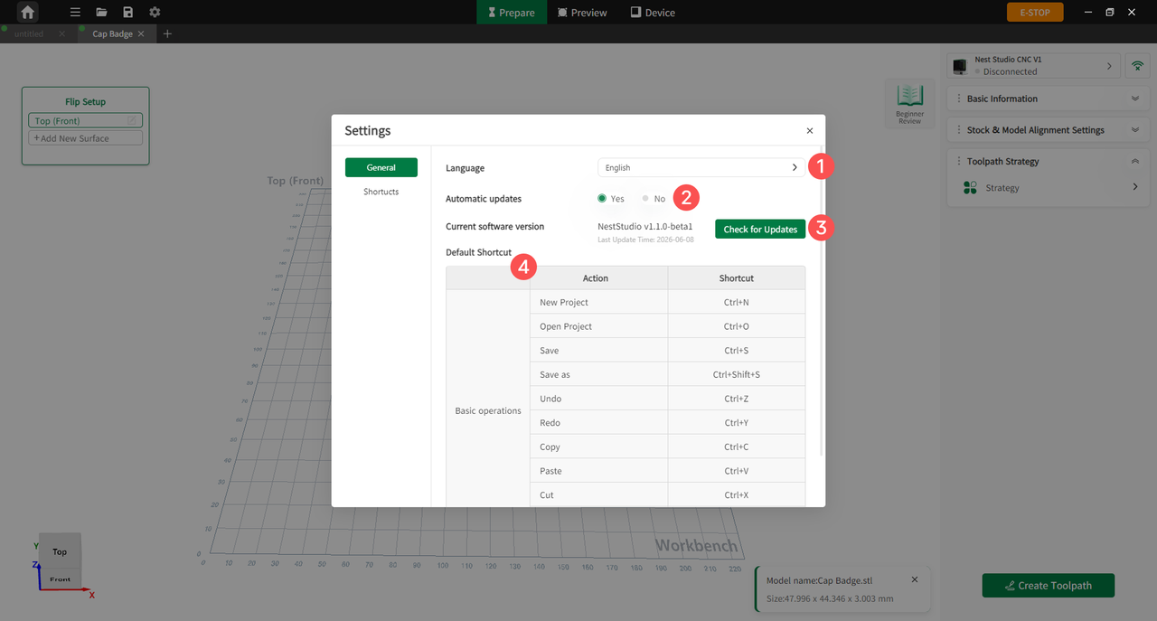
Figure 6-30 Settings
| No. | Name | Function |
|---|---|---|
| 1 | Language | Switch the software display language. The system language is detected automatically; if no matching language is available, English is displayed by default. |
| 2 | Automatic Updates | When enabled, the software automatically checks for new versions at startup to obtain feature updates and bug fixes. When disabled, users need to click Check for Updates manually. |
| 3 | Check for Updates | Manually checks whether the current software version is up to date. If a new version is detected, users can update the software according to the prompts. |
| 4 | Shortcuts | Displays the shortcuts for common software functions, such as creating a new project, opening a project, saving, undoing, copying, and pasting. |
¶ Software E-Stop
The Soft E-Stop is a core safety control function integrating device lock, device unlock, and software emergency stop functions.
When the device is in an abnormal state, this function can be used to lock or unlock the device to improve machining safety.
E-Stop states are indicated by different colors:
- Green: Device standby state
- Red: Device locked state; returns to green after unlocking
- Orange: Physical E-Stop state