¶ Equipment Specifications
| Item | Specification |
|---|---|
| Net Weight | 130 kg |
| Dimensions | 550 × 590 × 745 mm |
| XYZ Travel | 240 × 210 × 130 mm |
| Positioning Accuracy | ± 0.02 mm |
| Repeatability Accuracy | ± 0.008 mm |
| Spindle Speed | Max. 18,000 r/min |
| Constant Torque Range | 5000-12000 r/min |
| Tool Magazine | 5-station ATC with integrated Auto Tool Setter |
| Auto Tool Setting Accuracy | ± 0.005 mm |
| Operating Noise Level | ≤ 70 dB (Aluminum alloy cutting) |
| Continuous Operation Time | ≥ 8 h |
| Footprint | 550 (X) × 590 (Y) mm |
¶ Axis Specifications
| Axis | Max Travel | Speed | Backlash |
|---|---|---|---|
| X | 240 mm | 5000 mm/min | ≤ 30 μm |
| Y | 210 mm | 5000 mm/min | ≤ 30 μm |
| Z | 130 mm | 5000 mm/min | ≤ 30 μm |
¶ Power Supply Specifications
| Item | Specification |
|---|---|
| Spindle Power | 800 W |
| Power source | 110-240VAC |
| Operating Frequency | 50/60 Hz |
| Total Power | 1.6 kW |
| Full Load Current | 10 A Max |
| Phases | Single-Phase |
¶ Machining Dimensions
The following dimensions are reference values for the machinable range under typical installation and clamping conditions.
¶ 3-Axis Machining Dimensions
-
Tool magazine on the X-axis right side
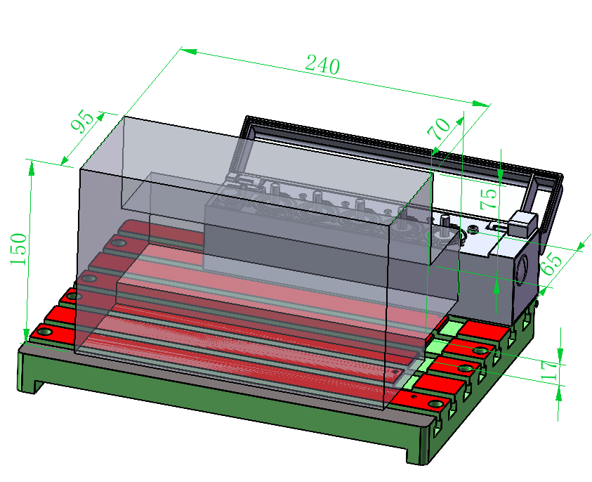
Figure 9-1 3-Axis Machining Dimensions
- Tool magazine on the Y-axis inner side
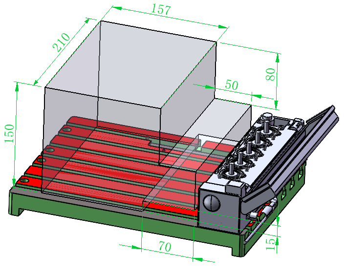
Figure 9-2 3-Axis Machining Dimensions
- Tool magazine removed
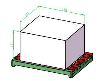
Figure 9-3 3-Axis Machining Dimensions
¶ 4-Axis Machining Dimensions
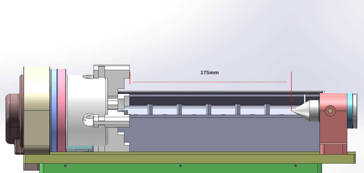
- Tool magazine placed along the Y-axis, with tailstock center
When clamping Φ80 mm stock, the maximum machinable diameter is Φ100 mm, and the machinable length along the X-axis is 175 mm.
- Tool magazine on the X-axis right side, with tailstock center
When the tool magazine is placed on the X-axis right side and the tailstock center is used, the machinable length along the X-axis is 70 mm.
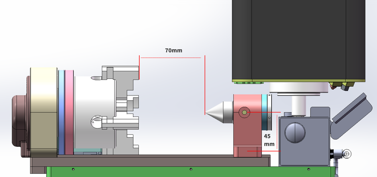
Figure 9-4 4-Axis Machining Dimensions
3.Tool magazine on the X-axis right side, without tailstock center
When the tool magazine is placed on the X-axis right side and the tailstock center is not used, the machinable length varies depending on the stock diameter:
- For stock diameters of Φ60–Φ100 mm, the machinable length along the X-axis is 103 mm.
- For stock diameters less than Φ60 mm, the machinable length along the X-axis is 130 mm.
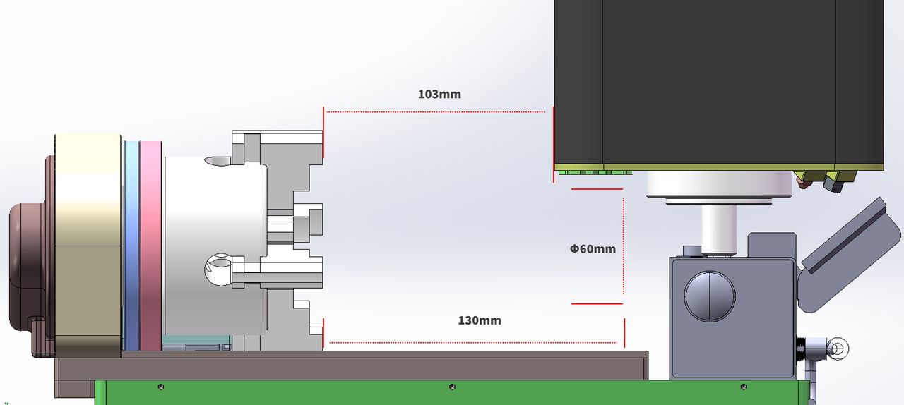
Figure 9-5 4-Axis Machining Dimensions
¶ Maximum Machinable Diameter in 4-Axis Mode
The 4-axis clamping space is Φ80 mm. When tool protrusion, base plate clearance, and safety clearance requirements are met, the maximum machinable diameter is Φ100 mm.
Taking a 50 mm tool as an example, if the tool clamping length is 15 mm, the tool protrusion length is 35 mm. The theoretical space in the 4-axis area is 160 mm. After deducting the tool protrusion length, the 13 mm thickness of the 4-axis base plate, and the 12 mm upper and lower safety clearance, the machinable diameter is:
50 mm - 15 mm = 35 mm
160 mm - 35 mm - 13 mm - 12 mm = 100 mm
Therefore, under these conditions, the maximum machinable diameter in 4-axis mode is Φ100 mm.
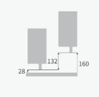
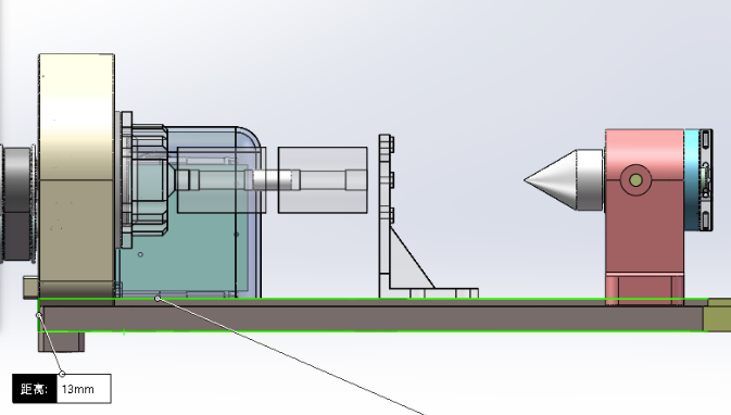
Figure 9-6 Maximum Machinable Diameter in 4-Axis Mode